
English
▼
Press ESC to close

1. What is a Burner?
Burners are classified into various types based on their different attributes.
By fuel type:
• Oil-fired burners
• Gas-fired burners
• Dual-fuel burners
• Biomass burners
Specifically:
• Oil-fired burners are further categorized into light oil burners (e.g., diesel) and heavy oil burners (e.g., waste oil).
• Gas-fired burners include natural gas burners, town gas burners, LPG burners, and biogas burners.
• Biomass burners utilize biomass pellets, producing clean, pollution-free combustion.
By combustion control mode:
• Single-stage burners
• Two-stage burners
• Modulating burners
By fuel atomization method:
• Mechanical atomizing burners
• Medium atomizing burners
By structure:
• Integrated burners
• Split-type burners
Split-type burners are primarily used in industrial applications. Their key feature is the separate installation of the combustion system, air supply system, and control system. This type is mainly suitable for large-scale equipment or special working environments such as high-temperature conditions.
In contrast, commercial burners are relatively inexpensive due to mass production and lower specialization requirements in the market supply chain. Split-type burners, however, command much higher market prices due to greater specialization demands and the frequent need for professional installation teams.
Burners are also classified by application:
• By usage object: Kiln burners and boiler burners (the latter being the commonly referred to “burners”)
• By application field: Industrial burners, civil burners, and commercial burners
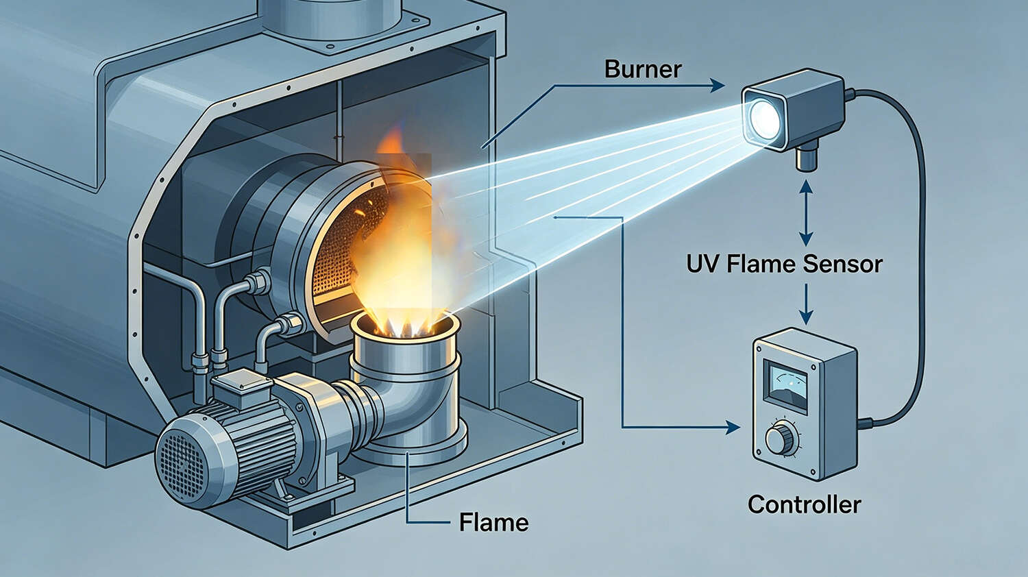
2. Why Real-Time Flame Monitoring is Required in Burners
Ultraviolet (UV) flame detectors are used for flame monitoring in gas and oil-fired industrial burners. These detectors are only sensitive to the ultraviolet radiation produced by flames, and do not respond to ambient light or high-temperature radiation from the furnace, offering strong anti-interference capabilities.
The system controls the ignition device for automatic ignition, simultaneously opening the fuel valve. If ignition is not achieved within the set time, the controller automatically closes the fuel valve and triggers an alarm. If ignition succeeds, normal fuel supply is maintained. Without real-time monitoring, severe accidents such as gas leakage and explosions could occur.
3. Current Types of Flame Monitoring Sensors
Flame detection in burners is typically performed by sensors that detect the presence of flame through optical signals, which can be used with ignition and control equipment. UV phototubes operate on the principle of ultraviolet radiation emitted by flame light, making them ideal for applications using various fuels (liquid or gaseous).
(1) Flame Sensors for Gas Burners
These sensors are suitable for flame detection in gas or mixed-fuel (gas and oil) burners.
A UV phototube consists of a gas-filled glass bulb containing two appropriately shaped electrodes. When AC power is supplied to the electrodes, if UV electromagnetic radiation (190–290 nm) strikes the phototube, electrons emitted by the negatively biased electrode and captured by the positively biased electrode begin to ionize, causing a discharge and generating an electric current.
Available models: UV1, UV2, UV3
Sensitivity options:
• Standard sensitivity
• /H: High sensitivity
Technical specifications:
• Nominal lifespan: 10,000 hours
• Maximum distance from UV source: 1 m
• Temperature range (UV1–3): -20°C to 50°C
• Temperature range (UV2): -20°C to 60°C
The flame sensor is insensitive to daylight and generally requires no shielding unless installed near gas-discharging lamps (e.g., neon lamps), which may affect sensor performance.
(2) Flame Detection Equipment for Oil-Fired or Blue-Flame Gas Burners
Gas oil combustion produces a very bright flame that is easily detected by standard phototube sensors. However, it also generates significant unburned/partially burned substances that gradually contaminate the combustion chamber. Proper combustion adjustment resolves this and improves flame quality to resemble that of gas, natural gas, or propane (blue flame).
Since phototubes are insensitive to blue flame light, flame detection in most gas burners relies on the ionization principle. This simply requires an electrically isolated metal rod (electrode) to be “immersed” in the flame. However, practical application is challenging: electrodes immersed in flame easily foul (eventually failing) and disrupt turbulence in the combustion chamber, causing serious issues.
Technical specifications (FDx series):
• Supply voltage: 220–240V ~ 50/60Hz
• Power consumption: 1 VA
• Spectral range: 290–350 nm (visible/UV band)
• Reception angle: 8°
• Operating temperature: -20°C to +60°C
• Relative humidity: 95%
Safety and installation guidelines for FDx sensors:
1. Position the device to ensure flame light strikes the 8° field of view.
2. Do not place inappropriate transparent materials (e.g., UV-filtering glass) between the sensor and flame.
3. Avoid installation near heat sources to prevent internal overheating and sensor damage.
(3) Flame Detection Equipment for Oil-Fired or Gas Burners with BRAHMA Safety Equipment (distributed by Isweek)
FDx/S sensors employ a silicon pre-amplified active element, specifically designed for blue-flame burner applications. The sensor’s UV detection limit is 310 nm. An integrated electronic interface ensures compatibility with all BRAHMA gas application equipment.
This sensor is particularly suitable for use with DS11, DS11P, DM11, DM11P, and GM592N/S. It is strongly recommended for single-electrode applications using DM11 and DM11P. Two versions are available: FD1/S (front-view) and FD2/S (side-view). High-sensitivity models are required for applications where the flame is distant from the detection point.
Note: FDx detectors are sensitive to the ultraviolet component of visible light. Installation in enclosed combustion chambers or environments fully shielded from visible light is recommended.
Characteristics:
• Supply voltage: 220–240V ~ 50/60Hz; 110–120V ~ 50/60Hz
• Power consumption: 1 VA
• Spectral range: 290–350 nm
• Reception angle: 8°
• Operating temperature: -20°C to +60°C
• Relative humidity: 95%
Wiring precautions:
• Keep FDx cables away from ignition devices or high-voltage lines.
• FD/S devices may only be used in conjunction with BRAHMA gas application ignition and flame control equipment.
4. Controllers
RE3 controls are designed for verifying flame presence in gas burners. RE3 flame detectors are primarily used in industrial applications and semi-automatic ignition control systems, especially when multiple burners require simultaneous control. An LED provides corresponding status indications.
Installation guidelines:
• Connect/disconnect controls only when power is off.
• Controllers may be installed anywhere.
• Ensure proper waterproofing measures.
Gas Safety Regulations and Fault Classification
Nowadays, people’s living standards have improved significantly. As a new type of energy and fuel, gas is widely used in daily life, bringing great convenience. However, gas has special inherent characteristics: explosiveness, toxicity, and flammability. Additionally, gas supervision is increasingly difficult, equipment maintenance and management are challenging, gas has a low safety factor, and inspectors face high risks during detection. Any malfunction in gas equipment can lead to extremely severe consequences.
Since gas is a public utility, pressurized, and possesses flammable, explosive, and toxic properties, emphasizing safe production is absolutely essential. This code stipulates that urban gas engineering design must meet requirements for safe production, reliable supply, rational gas use, and environmental protection.
Code for Construction and Quality Acceptance of City Indoor Gas Engineering (CJJ 94-2003) took effect on August 1, 2003. Its main contents include: General Provisions, Installation of Indoor Gas Pipelines, Installation of Gas Meters, Installation of Gas Equipment, and Inspection, Testing and Acceptance of Indoor Gas Pipelines and Gas Appliance Installation.
Reliability-Centered Maintenance (RCM) evaluates failures and ranks their criticality in the following order:
1. Potential Failure: A condition with no current direct impact on equipment, but which would result in severe consequences if it occurred.
2. Safety-Related Failure: A failure endangering personal safety and human life. Leakage from LPG storage tanks and wet spiral coal gas holders poses explosion risks. Corrosion and leakage of such equipment are classified as safety-related failures.
3. Operational Failure: A failure disrupting production operations and incurring direct repair costs. Malfunctions of Roots blowers (conveying mine gas to municipal gas holders), regional pressure regulating stations, and regulators are categorized as operational failures.
Non-Operational Failure: A failure generally not disrupting production but increasing repair expenses. Examples include malfunctions of machine shop tools, deep-well pumps, and standby diesel generators.